A DC motor made from a battery, wire, and a strong magnet.
Watch The Video:
 |
 |
 |
|
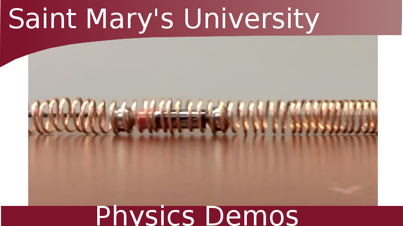
Solenoid Train |
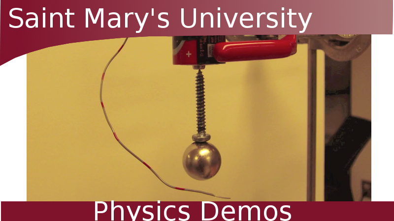
Homopolar Motor |
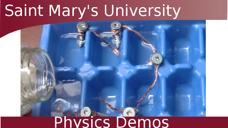
Electrochemical Circuit |
Teachable Topics:
- circuits
- Lorentz force law
- right hand rule
- magnetic fields
Theory:
Motors convert electrical energy into mechanical energy. Electrical energy can come from a voltage source such as a battery. Mechanical energy is able to perform work, such as rotating a cog.
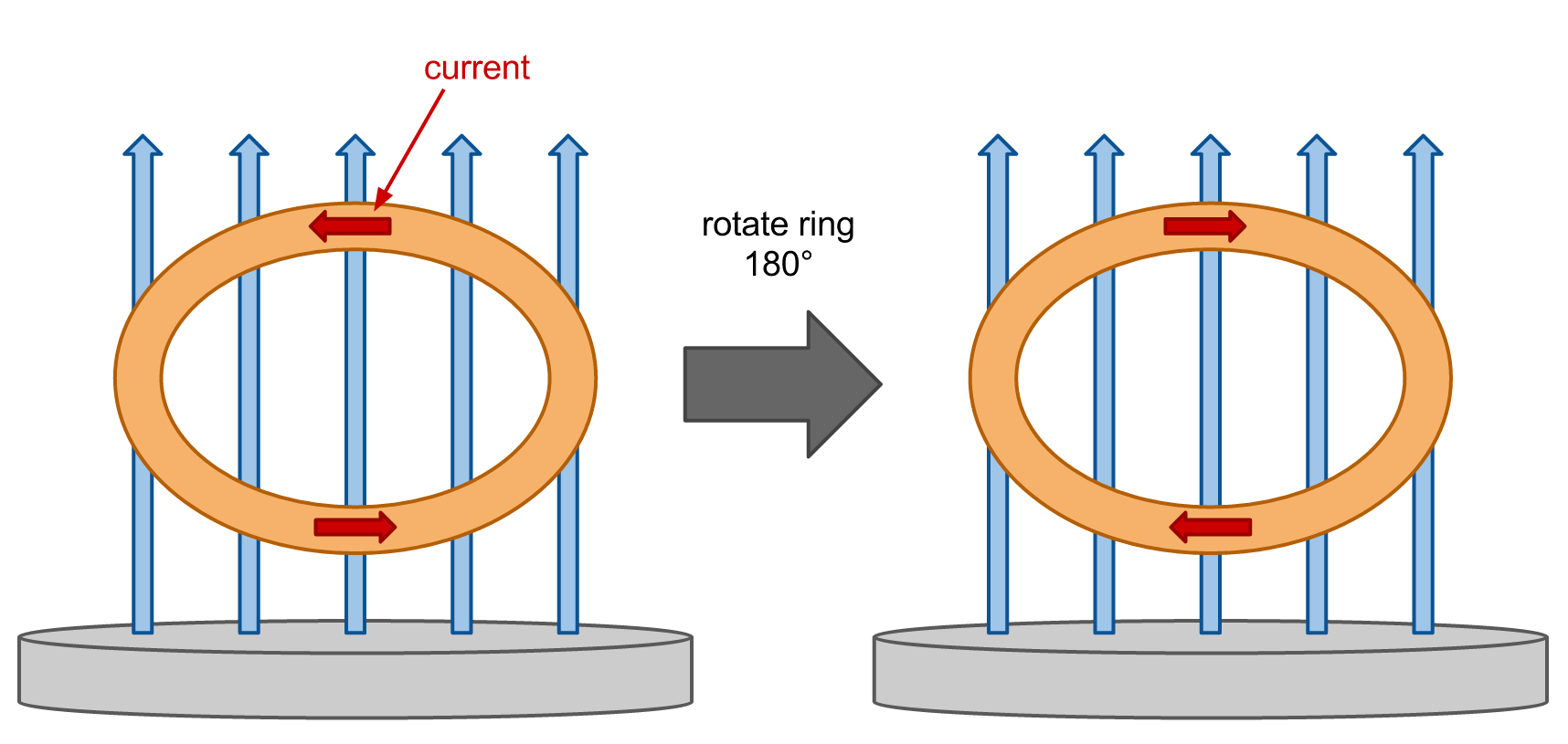
This simple motor works due to Faraday’s Law of Induction. The magnet below the coil generates a magnetic field. Depending on the orientation of the magnet, the field is either directed out of or into the magnet.

The coiled wire suspended above the magnet has current running through it, either clockwise or counterclockwise. When the wire is oriented vertically above the magnet, the top and bottom of regions of the coil feel a force from the magnetic field, as the current in these regions runs perpendicular to the magnetic field. However, the current in the sides of the coil runs parallel to to the magnetic field and so feels no force from it.

The Lorentz Force Law tells us that the magnetic force on a moving charge is perpendicular to the direction of current as well as the magnetic field. The magnetic force on a moving charge is given by:
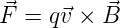
where q is the charge of the particle, v is its velocity, and B is the magnetic field. Since the direction of the charge’s velocity is the same as the current, we can use the right hand rule to determine the direction of the force on the top and bottom of the coil.

By the right hand rule, the bottom of the coil feels a force directed into the page while the force on the top of the coil is directed out of the page.

This force creates a torque on the coil, causing it to rotate.
When the coil has rotated 180°, current flows in the opposite direction. Unchecked, this would cause the coil to rotate in the opposite direction, 180° back the way it came. The ring not complete a full rotation and would simply rotate back and forth 180°.
To ensure the ring completes a full rotation, half of the wire must be insulated to stop the flow of current every half-rotation. The bottom of the wire is in contact the circuit, so when it rotates such the insulated side touches the circuit, no current will flow. With no current flowing, the ring keeps rotating in the same direction from inertia.
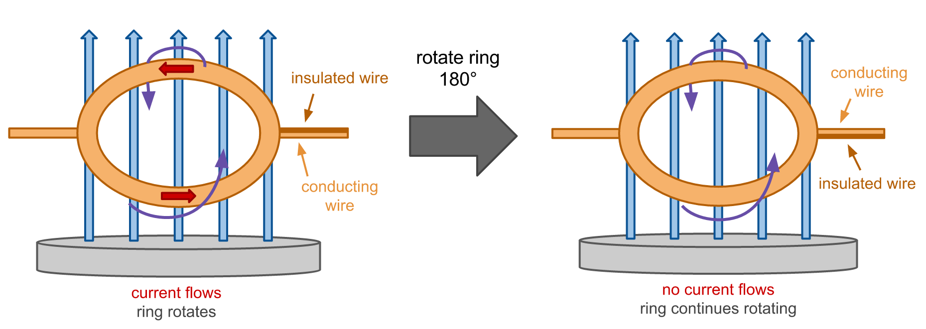
To ensure that half of the wire is insulated, strip the insulation off of half of the wire on one side of the coil, and strip all insulation from the wire exposed on the opposite side.
Apparatus:
- battery (9V)
- 2 metal posts
- magnet wire
- rare-earth magnet
- 2 electrical wires
- wire stripper
- switch
Procedure:
- drill a hole in each metal post, large enough for the wire to rest on the bottom without touching the top
- fix the metal posts and the battery (located between the posts) to a board
- using electrical wire, connect the battery to the two metal posts, with one end connecting to a switch
- coil the magnet wire uniformly to create a ring, leaving a straight segment at either end of the coil to sit on post
- strip the insulation from the straight ends of the magnet wire
- strip the whole wire on one side
- strip only the top on the other side
- rest the coil on the metal post
- turn on the switch to complete the circuit
- the coil may need an initial nudge to get spinning